Timothy Thiele holds an associate degree in electronics and is a member of IBEW Local #176. With more than three decades of expertise, he specializes in wiring for residential, commercial, and industrial projects.
Project Summary
- Hours of Operation: 8 hours
- Overall Duration: 8 hours
- Output: Produces a single circuit breaker panel with 15 to 20 circuits.
- Proficiency Level: Expert
- Projected Expense: Between $700 and $950 (excluding labor costs)
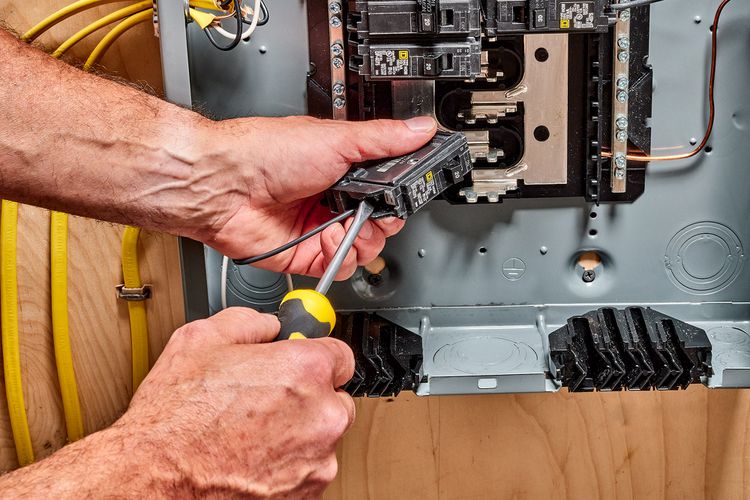
This summary outlines the process by which a qualified electrician links a home’s electrical circuit breaker panel to the main service wires that enter the residence, as well as to the separate branch circuits within the house. Typically, this task is performed by a licensed expert rather than a do-it-yourself enthusiast.
In this scenario, we consider that the electrical panel is mounted on the wall of a utility space, close to where the main feeder wires enter the house, and that all branch circuit cables and conduit installations are already in place. During the construction of a new home or a significant rewiring project, the final phase involves linking all the wires to the circuit breaker panel, as outlined in this guide. Discover the procedures that experts follow to wire a breaker box.
Contents
- 1 Safety Precautions
- 2 Requirements for Your Project
- 3 Instructions
- 3.1 Inspect the feeder wires for electrical supply.
- 3.2 Install the Circuit Breaker Panel.
- 3.3 Set up the primary service cables.
- 3.4 Attach the primary grounding wire.
- 3.5 Link the primary service neutral.
- 3.6 Link the Primary Circuit Breaker
- 3.7 Install Wires for Circuit Branches
- 3.8 Join the ground wires of the branch circuit.
- 3.9 Link the branch circuit breakers.
- 3.10 Finalize the Setup
Safety Precautions
This type of project is not suitable for the average homeowner. Linking a breaker panel can be hazardous for those without expertise, and in many areas, local building regulations may prohibit individuals from undertaking such significant electrical tasks on their own. Additionally, it necessitates collaboration with the electrical utility provider.
Looking for additional assistance? Reach out to a local electrician.
Our collaborators can assist you in evaluating estimates from highly-rated experts in your vicinity.
Requirements for Your Project
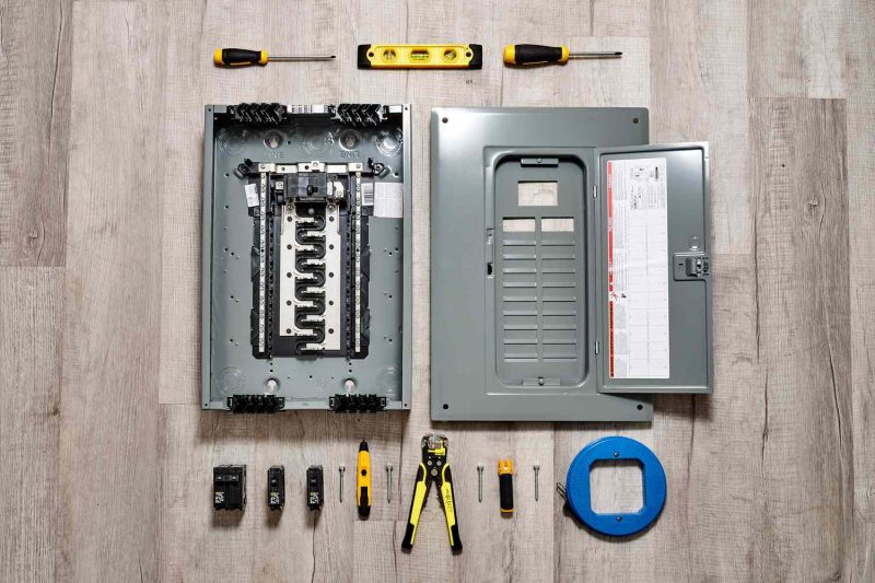
Devices / Instruments
- Electrical voltage meter
- Screwdriver or carving tool
- Hammer
- Fish tape for electricians
- Level
- Cable stripper
- Cable insulation removers
- Drill
Materials
- Electrical panel for circuit breakers
- Optional wall anchors
- Circuit breakers for 120 volts and 240 volts
- Insulating tape
- Plywood (if desired)
- Labels
Instructions
Inspect the feeder wires for electrical supply.
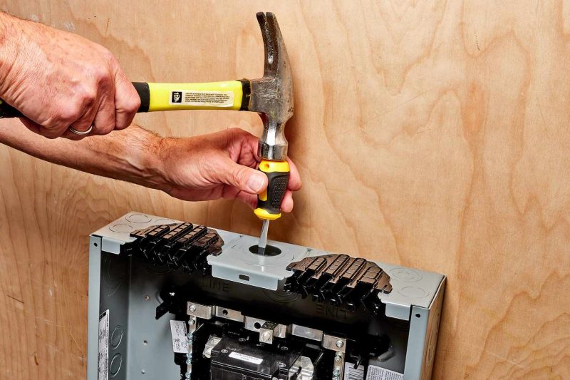
Install the Circuit Breaker Panel.
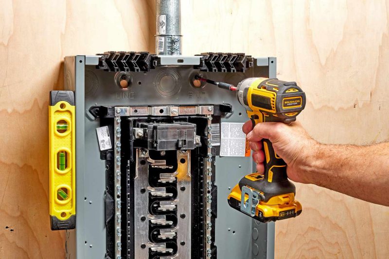
The electrician then places the circuit breaker panel in position, ensuring it is level before fastening it to the wall using screws or anchors inserted through the panel’s back. If the pre-drilled holes do not match the wall studs, they might create extra holes or attach a plywood board to facilitate the installation. If the main service wires come into the house through a conduit, the panel is aligned to allow the conduit to fit into the conduit fitting that is already installed on the service panel.
Set up the primary service cables.
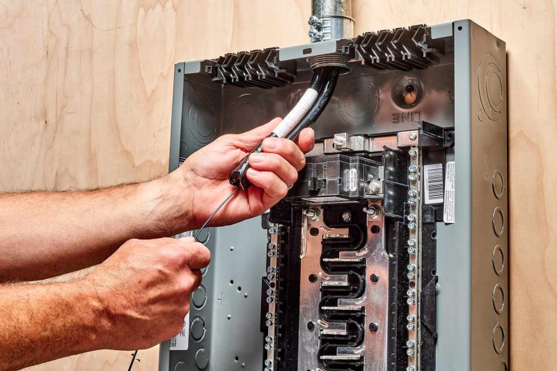
The electrician will now insert a fish tape through the main service conduit opening, starting from the panel and extending to the external entry point where the main service wires are located. Typically, there are three main service wires: two black wires that are hot and one white neutral wire. The main service wires are attached to the fish tape using electrical tape and are then pulled back into the breaker panel. Due to the size and rigidity of the wires, it may be necessary to have an assistant push the wires from the outside while the fish tape is pulled from the inside. A sufficient length of wire is pulled into the panel to facilitate connections at any point within the box.
Attach the primary grounding wire.
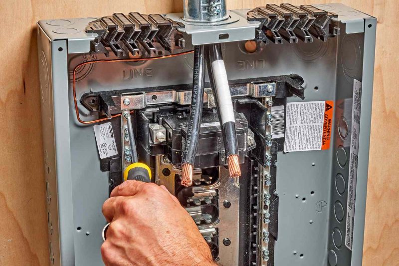
The primary grounding conductor, typically a sizable bare copper wire, is routed into the electrical panel and linked to the primary grounding point. This is often a metal lug located on the rear of the metal panel or at the terminal of the grounding bus bar. This principal grounding wire is generally attached to a grounding rod. In certain setups, there might be an extra grounding wire employed to connect metal water pipes to the systemboth of these can be attached to the same grounding lug within the service panel.
Link the primary service neutral.
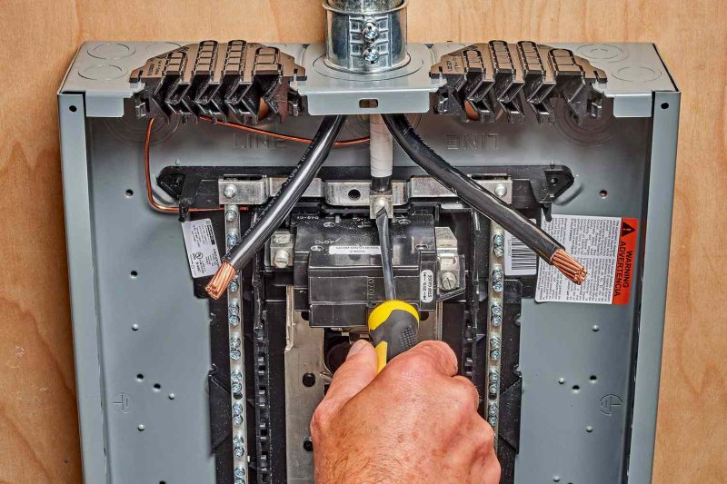
The primary neutral wire for the service has been linked to the neutral bus bar. The positioning of the neutral bus bar can differ based on the manufacturer of the panel, but it is consistently situated at a distance from the two hot bus bars. This bar is typically silver in color and features numerous smaller screws and connection points, along with a larger opening designated for the main service neutral wire.
Link the Primary Circuit Breaker
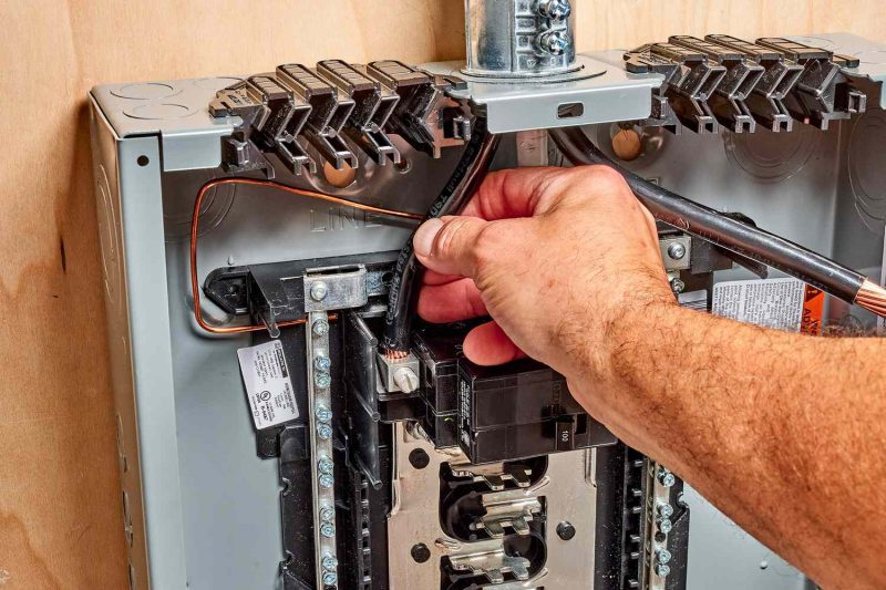
The electrician is currently shaping the two black service wires to facilitate a smooth connection to the main breaker. Typically, the main breaker is a sizable 240-volt circuit breaker positioned at the top of the panel. This breaker regulates the total power supply to the home and links to both hot bus bars that extend vertically through the panel. Next, the electrician carefully removes just the right amount of insulation from the ends of the service wires to connect them to the terminal lugs of the main circuit breaker. It is crucial to avoid leaving any excess exposed wire, as this could pose a safety risk if the bare wires touch other wires. Finally, the stripped ends of the two main service wires are inserted into the lugs of the main breaker, and the screws are tightened firmly. The panel is now prepared for the addition of individual branch circuits and their respective breakers.
Install Wires for Circuit Branches
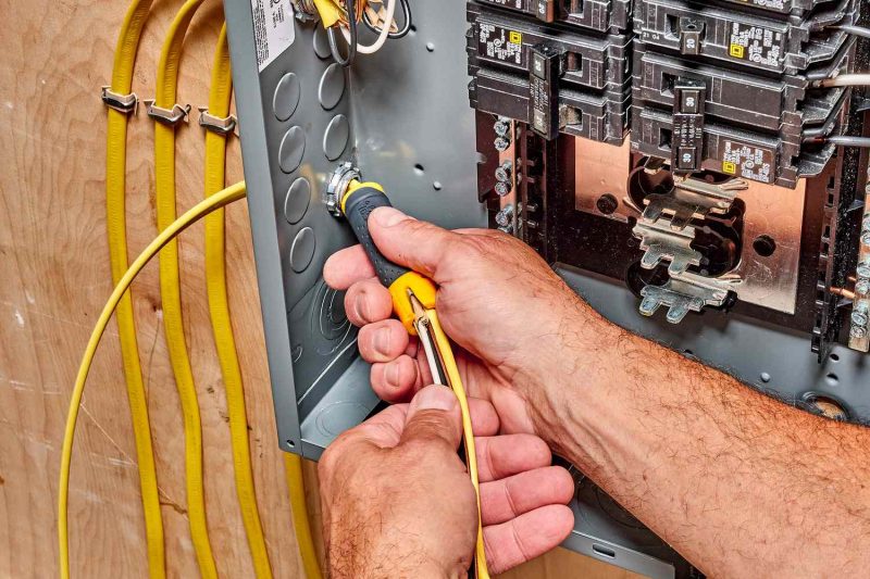
The electrician will now route the wires for the various branch circuits into the panel. If the wires come through a metal conduit, fish tape will be utilized to guide them into the panel. In the case of NM wiring, NM connectors will be attached to the panel, securing the cables with screws that fasten onto a yolk. Ample wire will be pulled into the panel to allow for any adjustments, with the surplus wire coiled along the panel’s inner edges. The outer plastic sheathing of the NM cable will be trimmed back, leaving a small section intact at the panel entry. For each wire, the electrician will carefully strip a short section of insulation from the conductive wires, using a specialized stripping tool to prevent any damage to the metal.
Join the ground wires of the branch circuit.
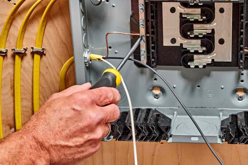
The electrician proceeds to link all the green and uncoated copper wires designated for the branch circuits to the grounding bus bar located within the panel. The wire ends are placed into the slots of the bus bar, and the setscrews are securely fastened.
Link the branch circuit breakers.
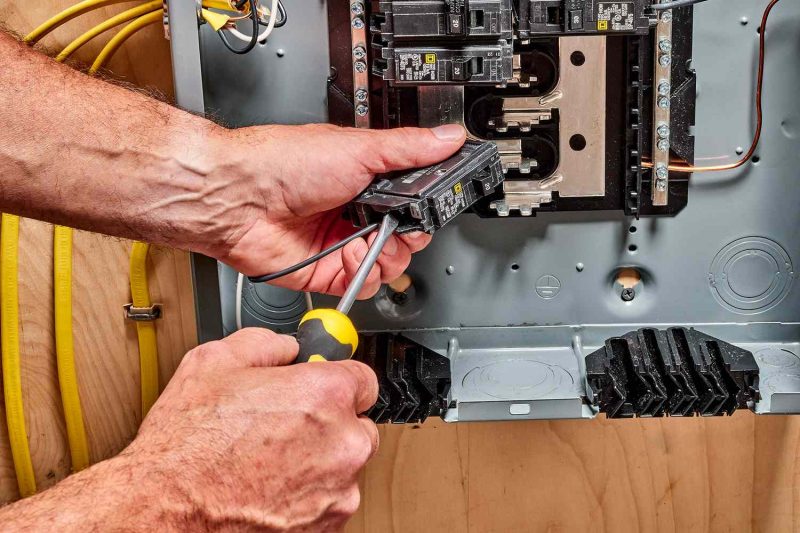
Each branch circuit’s circuit breaker is now connected individually. The selected breakers are specifically designed to align with the necessary amperage and voltage requirements, as well as to comply with code standards. Electricians undergo thorough training to determine the suitable breaker type for each circuit. For instance, some breakers are designed as GFCI, others as AFCI, and some may be combination breakers. The specialized breakers feature a coiled pigtail wire, while standard breakers lack pigtail wires and are equipped with lugs for connecting hot wires. The installation process starts with connecting the circuit’s neutral wire. For standard breakers, the neutral wire is linked to the neutral bus bar within the panel. In contrast, for AFCI, GFCI, or combination AFCI breakers, the neutral wire is directly connected to the breaker via a screw terminal labeled Panel Neutral or White. (Note: In 240-volt circuits, there are no white neutral wires, as both wires are hot.) The next step involves connecting the circuit’s hot wire, which is typically black or red. For AFCI or GFCI breakers, this wire is connected to the terminal labeled Load Power or Black. Lastly, for AFCI or GFCI breakers, the coiled white pigtail wire is connected to the neutral bus bar in the panel. Once all circuit wires are connected, the circuit breaker is positioned into its designated slot in the panel. The installation process may vary slightly by manufacturer, but it typically involves hooking the front edge of the breaker over the panel’s clips and then pushing down until it clicks into place. Excess wire is neatly arranged along the panel’s inner edges, with ample length left to facilitate future repairs or replacements.
Finalize the Setup
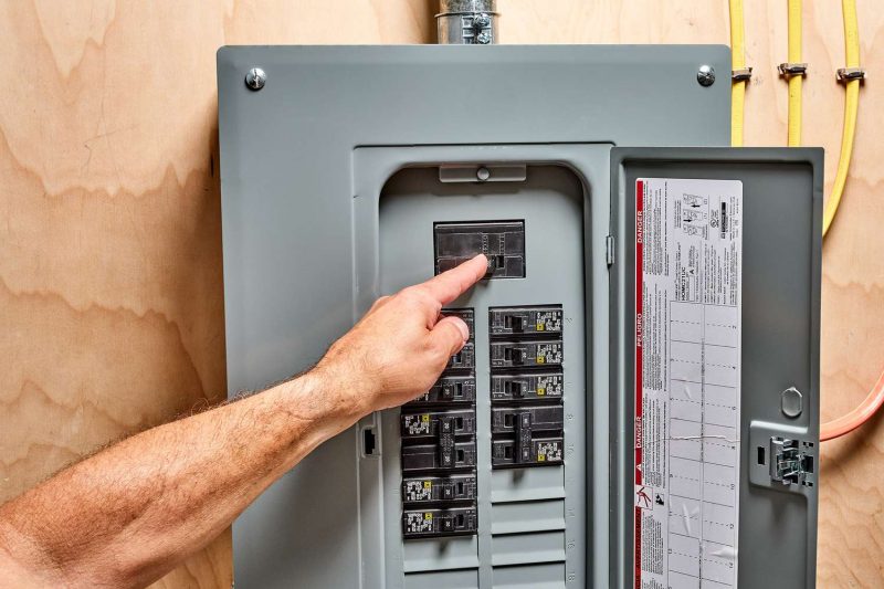
The circuit breaker panel cover has been put in place, and the electrician has requested the utility company to restore the power supply. Next, the electrician activates the circuit breakers, ensuring that every circuit in the home is functioning properly. To conclude the job, the electrician labels the panel to indicate the purpose of each circuit. This labeling will assist the homeowner or any future electrician in easily identifying and turning off specific circuits when needed.
